

Are you Stepping up, or about to Stagger?
A lot of the time, terraced properties can be built in perfect alignment; but at other times, when building on sloping sites or with a mixture of house types to give a pleasing streetscape, steps and/or staggers will need to be accommodated.
Stepping on the ground
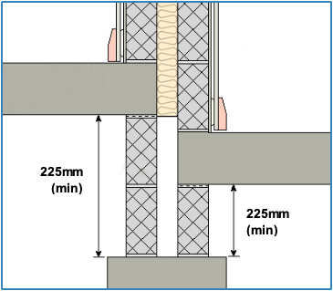
The specifications for the cavity masonry walls stipulate that the cavity should extend a minimum of 225mm below the structural floors, and this applies just the same to steps. This is to mitigate the potential for sound transmission via the foundation connection. Hence there should be nothing (other than appropriate wall ties) that would create a rigid connection between the wall leafs in this zone.
Cavity insulation (as relevant to the Robust Detail) needs to cover the area of wall that is separating one dwelling from another, so in terms of sound insulation it is not required where the wall goes down to become an external element.
The light steel and timber frame walls have just the same considerations – the only difference being that although these wall types do need to maintain the cavity through the ground floor, there is no minimum dimension for the cavity to be continued below, although it is best to continue the cavity down for a reasonable distance.
Stepping a head
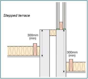
Depending on circumstance, the head of the wall might be formed in a number of ways. With masonry walls, perhaps the simplest being that the two leafs continue up to the level of the highest roofline. As with the foundation detail, once the wall becomes exposed, it can be treated largely as an external element, so normally a stepped cavity tray is fitted in line with the lower roof, and above this the cavity wall construction would follow that used elsewhere for the external wall elements. As with the foundation detail, there should be nothing (other than appropriate wall ties) creating a rigid connection between the wall leafs in this zone.
In roof voids, single or twin-leaf spandrels can be incorporated. As noted on page 5 of Appendix A1, the wall must extend a minimum of 300mm above the ceilings, and this applies just the same to any stepped situations.
It is also possible to have one block leaf continuing up (which might be required to form an exposed gable) with a spandrel panel of the required specification sitting on the other leaf.
Light steel and timber frame walls can also continue up to the level of the highest roofline, with a lightweight external cladding provided to the outer leaf once it is exposed.
Staggering back and front
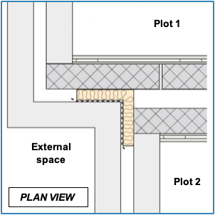
With cavity masonry walls, there are two ways to construct the junction of separating wall to external wall to form a stagger.
This diagram is what would typically be seen on page 2 of the Robust Detail where one separating wall leaf continues through for the extent of the projection.
This is intended for small staggers, but if you have a large stagger and, particularly if there are less thermally-efficient blocks used in the separating wall, this detail could have implications on the thermal performance of the building envelope.
In these cases it may be more appropriate to refer to the diagram below, as seen on page 6 of Appendix A1.
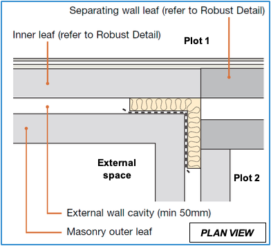
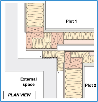
In this configuration, both separating wall leafs stop at the same point, and the external wall specification takes over for the projecting wall. As in all cases, the block type used in this inner leaf has to be listed as one of the flanking options in the separating wall Robust Detail.
Additionally, the straight joint at the transition between the block types can be at risk of cracking, so it may be worth getting the approval of building control bodies and warranty providers early on, as they may have requirements and conditions in relation to this.
Thermal, as well as structural considerations, also come into play with timber frame, in these cases there is sometimes the need to change to deeper studs.
It is acceptable to do this with Robust Details, provided the required minimum 50mm cavity is always maintained between the timber frames.
So as can be seen in this diagram, the narrower frame section of the projecting separating wall leaf has to extend further to maintain the cavity and avoid creating a pinch-point.
Whilst these principles can also be applied in flats, the arrangements can become more complex and, therefore, specific guidance might need to be sought to determine whether or not details can be considered compliant.
Of course, in all cases other regulations and standards should also be considered.
If you have any techncial enquiries please do not hesitate to contact our technical team on 03300 882140 or email: technical@robustdetails.com
Return to the Top Tips page